Anyone who wants to set a lift table flush into the hall floor is not just planning a piece of equipment, but also a piece of structure: the pit. Its dimensions, its edges, the supply lines and the drainage all help decide whether later operation runs smoothly. This article explains when a pit installation is worthwhile and when a lift table without a pit is the simpler choice, how the pit dimensions and pit depth are derived from the closed height, what to watch for with edge framing, supply lines and drainage, which safety requirements apply at the pit edge, and how, with a pit drawing, an installation drawing and CAD data, you can finish planning the pit before it is built.
When does a pit installation make sense?
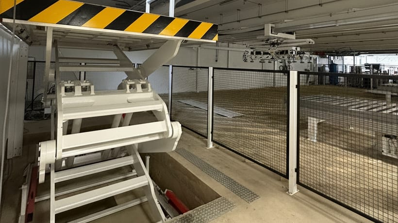
The goal of a pit installation is always the same: the lowered platform finishes flush with the hall floor. Pallets can be transferred at the same level, pallet trucks and forklifts drive on without a ramp, and the lift table disappears into the floor when it is not needed. This is worthwhile above all at permanently installed workstations and transfer stations with a high usage frequency, with large load capacities and everywhere the platform is meant to be driven over.
In all honesty, the opposite is also true: for many applications the pit is not needed at all. Flat-form lift tables have such a low closed height that they can be driven onto at floor level using an access ramp, entirely without groundwork, while remaining relocatable. So anyone who has the choice weighs it up: the pit costs a one-off building effort and ties down the location, but in return delivers the permanently cleanest solution for flush working. The rest of this article applies to the case where the decision for the pit has been taken.
Calculating pit dimensions: length, width and depth
The most important figure is the pit depth, and it is pleasingly simple to determine: the pit must always be at least 5 mm deeper than the closed height of the fully lowered lift table, so that the platform finishes flush with the floor. This makes the series the central planning decision. Flexlift flat-form lift tables of the FM series have a closed height from 55 mm, the FE and F-CE series from 70 mm; such tables make do with a very shallow recess that can sometimes be accommodated within the screed. Compact lift tables of the FK series start at a closed height of 180 mm, double-scissor lift tables FK-D for large lift heights at 350 mm; here the recess becomes a genuine pit in the foundation.
For length and width a widespread rule of thumb applies: the platform dimension plus around 30 mm of clearance, so that the platform can travel freely and the surrounding joint still stays narrow. What matters here is that such reference values are no substitute for proper engineering. Binding are the dimensions from the pit drawing for the specific model, because platform size, power-unit position and accessories change the requirements in detail. How you obtain this pit drawing is shown in the section on planning data further below.
Preparing the pit: edge framing, supply lines and drainage
A good pit is more than a hole in the floor. The pit edge is typically framed with an embedded steel angle: it protects the concrete edge from the traffic of pallet trucks and forklifts and forms a clean, dimensionally accurate seat for the joint to the platform. The pit floor must be level and load-bearing, so that the lift table sits firmly and the load is transferred evenly into the foundation.
The path of the energy should also be planned early: hydraulic and electrical supply lines reach the table most easily through a conduit that is set when the concrete is poured. Flexlift lift tables offer room to manoeuvre here; depending on the series, the power supply is possible from above as well as from the side, and the hydraulic power unit can also be placed outside the pit, which makes maintenance easier. For outdoor installation or in damp areas, finally, the drainage belongs on the plan; whether an oil separator is additionally required for a water drain is the customer's responsibility to verify; the local building regulations are decisive. A two-component oil-resistant pit coating is also recommended: it protects the concrete should the lift table, or an industrial truck standing on the platform, lose oil.
Safety at the pit edge: EN 1570 and SUVA
With a floor-level installation a special situation arises: the lowering movement ends at floor level, and nothing may be trapped between the platform edge and the pit edge. The governing standard is EN 1570-1, whose basic principle is protection against crushing and shearing points. Flexlift addresses this by design: the flat-form series carry a foot-protection contact edge running all the way around, which stops the lowering movement on contact, and does so on a purely hydraulic circuit, that is without electrical components on the table. As accessories, electrical safety contact edges and a bellows running all the way around are also available, which as reach-in and reach-under protection shields the scissor mechanism.
Relevant for Swiss operations: Flexlift lift tables are approved to EN 1570 and recognised by the SUVA. This means the pit installation rests on the same normative basis as free-standing installation; the pit itself changes nothing about the operator's obligations, but makes a clean execution of the edges and joints all the more important.
Drive-over capable up to 6 tonnes wheel load: the pit as a traffic area
An underrated advantage of the pit installation: the lowered platform can become part of the traffic area. For this Flexlift offers drive-over capable versions and, as an accessory, platform reinforcements for wheel loads of up to 6 tonnes. Forklifts and pallet trucks then cross the pit in normal operation, the hall floor stays drivable throughout, and the lift table only works when it is needed.
This requirement is particularly common at loading points, where lift tables bridge height differences between the ramp, the floor and the loading bed. Which solutions are suited to logistics and loading is shown on our page Lift Tables for Logistics and Warehousing; the design for the actual wheel loads belongs in the engineering in every case.
The digital planning dataset: pit drawing as DWG and PDF, installation drawing and CAD/STP
The pit is best planned completely before the first drill is applied, and for that it takes data rather than estimates. For the chosen model Tirugo supplies a project-specific pit drawing as DWG and PDF: as a DWG directly reusable in your CAD planning, as a PDF for building specialists and execution on site. Added to this are installation drawings and dimension sheets for the series.
For 3D planning it goes a step further: 99 percent of all Flexlift and PETec components are available as an STP file on request. The neutral STEP format can be imported into common CAD and plant-planning software, from the layout of the hall to the clash check around the pit, the supply lines and the conveyor technology. That this data is dependable comes down to its origin: Flexlift designs its lift tables itself with AutoCAD in 2D and Inventor in 3D, and the pit installation is available ex works as a special version including accessories. So you plan with the same geometries that are later built.
From the CAD model to the BIM model: what works and what does not
More and more often, specialist planners ask for data for the building model. Here the starting position is comfortable: the complete Autodesk environment is supported, from AutoCAD and Inventor through to Revit. On request you receive Revit data and further standard formats for BIM planning, such as IFC, alongside the neutral CAD formats STP/STEP and DWG for all other systems. The STP file can be imported into practically any CAD and plant-planning software and carried over into BIM workflows by specialist planners. Part of an honest assessment is this: the geometry model does not carry attributes such as load capacity or lift by itself; these values come from the data sheet and are added in the model. And a digital twin in the strict sense, that is an image linked to live operating data, is something a static CAD model is not in any case.
For practical purposes this means: Revit or IFC data for the building model, or the neutral STP geometry, dimensions from the pit drawing, key figures from the data sheet, and with that a lift table is cleanly represented in the building or factory model. Since public clients in Switzerland increasingly require digital building models, it is a tangible advantage when the equipment feeds into the planning with dependable 3D data from the outset.
Are you planning a pit installation, or would you like to check whether a flat-form solution without a pit is enough for your application? Send us the load capacity, the platform dimensions, the lift and the installation situation, and you will receive the right recommendation together with a pit drawing via our contact page.
Frequently asked questions about pit installation
How deep does the pit for a lift table need to be?
The pit must always be at least 5 mm deeper than the closed height of the fully lowered lift table, so that the platform finishes flush with the hall floor. It therefore depends directly on the series: Flexlift flat-form lift tables of the FM series have a closed height from 55 mm, the FE and F-CE series from 70 mm, compact lift tables FK from 180 mm and double-scissor lift tables FK-D from 350 mm. Binding are always the dimensions from the project-specific pit drawing for the chosen model.
What dimensions does the pit for a scissor lift table need?
As a rule of thumb the pit is made slightly larger than the platform; around 30 mm of clearance in length and width is common, so that the platform can travel freely and the joint stays narrow. The depth is the closed height of the lowered table plus at least 5 mm. The pit edge is typically framed with an embedded steel edge angle. What counts are the details in the pit drawing for the specific model, which Tirugo supplies as DWG and PDF.
When is a pit installation necessary and when is a lift table without a pit enough?
A pit installation is worthwhile when the platform is to finish permanently flush with the floor, for instance so that pallet trucks and forklifts can drive on without a ramp or loads can be transferred at the same level. For many applications it also works without a pit: flat-form lift tables with closed heights from 55 mm can be driven onto at floor level using an access ramp, entirely without groundwork. The choice depends on usage frequency, load capacity and the structural situation.
Does the pit need drainage or an oil separator?
That depends on the installation location. For outdoor installation or in areas with moisture and cleaning water the pit should be given drainage; whether an oil separator is additionally required for a water drain is the customer's responsibility to verify; the local building regulations are decisive. A two-component oil-resistant pit coating is also recommended, protecting the concrete should the lift table or a parked industrial truck lose oil. These points belong in the planning early on and are taken into account in the project's pit drawing.
Can a lift table in the pit be driven over with a forklift?
Yes. Flexlift offers drive-over capable versions in which the lowered platform becomes part of the traffic area. As an accessory, platform reinforcements for wheel loads of up to 6 tonnes are available, so that forklifts and pallet trucks can cross the pit as normal. The design is matched to the actual wheel loads and the usage.
Which planning data does Tirugo provide for pit installation?
For the chosen model Tirugo supplies a project-specific pit drawing as DWG and PDF, plus installation drawings and dimension sheets. For 3D planning, 99 percent of all Flexlift and PETec components are available as an STP file on request; the complete Autodesk environment is supported, and on request you receive Revit data as well as further standard formats for BIM planning, such as IFC. The neutral formats STP/STEP and DWG cover all other CAD and plant-planning systems. This means the pit can be planned before it is built.